3 things went wrong
October 7, 2017Hurricane Florence!
September 27, 2018OK it turns out that my teachers in college, a ton of engineering textbooks, and the internet in general all seem to understand what wings do. Also my airplane has wings, and those wings are designed to interact with the air as much as possible, so I can flight-test my airplane at any time (and I constantly do) to collect information about what the wings in said airplane do. And then I use the information from the several sources quoted above to really dial in the flight dynamics in X-Plane. Without question on my death-bed I will look back on my many flights flown while frantically scribbling down notes and flying the airplane at the same time fondly. This is a challenge that not enough people get to enjoy, and then turning that knowledge into a simulator that then turns into money for me… well, let’s just say I have very little to complain about.
ANYHOO, a ton of people including me know what sort of forces wings put out.
But what about airplane FUSELAGES?
Who knows THAT?
My teachers never really told me: they just could not give a specific answer in school.
Aero textbooks never tell me: They can’t because every fuselage is different. They can’t give a single good answer.
The internet doesn’t seem to tell me: All the references say that it varies with fuselage shape, and some give forces but not WHERE those forces are centered, which is surely important!
Flight test can’t really tell me: My airplane is controlled by it’s WINGS so much that I can’t really find the forces of the FUSELAGE!
Now, in X-Plane, the WINGS are handled extremely well… but what about the FUSELAGE forces?
Those are not nearly as accurate for the reasons stated above.
Now, we DO have references online for the drag of a cylinder going thru the air sideways, and we DO enter the fuselage coefficient of drag in Plane-Maker for when the fuselage is aimed perfectly into the air, but what about all the cases in between? What about when the fuselage is SORT OF slipped in the air, as happens every slip or imperfect turn crosswind take-off or landing? What about THOSE cases? While we can find decent estimates for the FORCES online ,I can’t find a good estimate of WHERE those forces are centered.
THAT is what I need to know to get the pitching and yawing of the airplane correct in X-Plane, especially in crosswinds.
So how do I find where these forces are centered?
The normal stability-test in cases like this is to SWING A MODEL AROUND ON A STRING, and see if it is stable.
But that is no green here because:
1: The location of the center of gravity will alter the test results
2: When swinging the thing around, you can tell if it is pointing up or down, but cannot really tell if it is pointing towards you or away from you, which is surely important in determining what the thing is trying to do.
3: I don’t need to see IF a model is stable: I need to see WHERE it’s stability-point is, requiring me to experiment with a large number of models or attach-points to find that neutral-point about which the model is just BARELY stable.
So clearly I need a generic fuselage model that has a variable-length body, and a wind tunnel where I can attach the model at a precisely-defined point to see about what point, exactly, the body wants to rotate.
Since I don’t have a wind tunnel, how about a ROLLING ‘wind tunnel’? A machine that will move my generic fuselage model through the air so that I can find it’s aerodynamic center of pressure? Such a machine must allow the test article to be mounted ABOVE any airflow around the rolling wind tunnel, in the CENTER so the flow is symmetrical, and the rolling wind tunnel should be able to drive itself on a deserted road outside of town so I can observe the test article while the wind tunnel drives itself.
What would such a setup look like?
Well, how about like… THIS?!?!
![]()
So here is the interesting thing about this:
I just used parts from my usual suite of model rocket parts to build this generic fuselage, and I made it so that the nose and tail of the rocket can be easily lengthened or shortened to adjust the body-length both fore and aft of the pivot-point. I set the autopilot to hold a steady low speed on a straight deserted road while holding the model well clear of the streamlines around the car and bang: Tesla wind tunnel.
So here is the question:
Where is the aerodynamic center of a generic fuselage?
Put another way: When there are side forces from a side-slip, where is the center of where those forces act?
What you cannot tell from the picture above is that the rockets swings like a weathervane: The steel rod coming out of the bottom of the rocket is going into a SLEEVE like a shower-curtain rod, so the rocket swings left and right with no friction at all: It is like a weathervane with no fins. (again: X-Plane already knows all about how the fins would work.. it is the BODY I am working on here).
So, if we EXTEND the NOSE of the fuselage so there is MORE fuselage in FRONT of the pivot than BEHIND, then the fuselage should swing around backwards! UNSTABLE!
So, if we EXTEND the TAIL of the fuselage so there is MORE fuselage BEHIND the pivot than IN FRONT, then the fuselage should point like a weathervane! STABLE!
So, if we SET the NOSE AND TAIL of the fuselage so we neither weathervane nor flip around, then we should have found our aero center! NEUTRALLY STABLE! THE POINT ABOUT WHICH THE FORCES ACT IS FOUND! YIPPEE!
So we just have the car drive while we see how the rocket wants to pivot with various-length fore and aft sections until we find the perfect lengths that have the thing be neither stable nor unstable: The neutral-point. And apply the forces in X-Plane there.
Sound like a plan?
Well, it ain’t.
As it turns out from many ‘flight’ tests in the ‘wind tunnel’, the neutral-point MOVES! It MOVES depending on the sideslip! HAR!
So what I see are various different AMOUNTS of side-slip that the body wants to generate depending on how far back from the nose the mounting-point is!
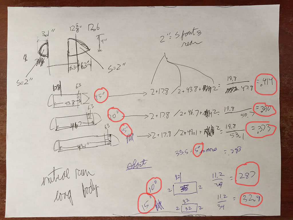
And HERE is the data, scribbled down after the most-reliable test-sessions (least wind, stablest speed, etc)
How MANY degrees the rocket wobbled circled on the LEFT, WHERE the rocket pivots circled on the RIGHT (0.0% mounted right at the nose, 50% mounted in the center, 100% mounted right on the tail… positions tried here are 41.4%, 39.0%, 37.3%, 28.7%, and 28.3%):
So what are we seeing here?
The farther-aft the mounting point, the more the nose would yaw left and right (45 degrees either side of center when mounted 41.4% of the way back along the body!)
The farther-forward the mounting point, the less the nose would yaw left and right (5 degrees either side of center when mounted 28.3% of the way back along the body!)
So what is this data trying to tell us?
When you know one or two really basic things, it suddenly becomes obvious:
WINGS (which we know VERY well) are VERY well known to pivot about their 25% chords. In other words, if you mounted the wing about the 25% chord, it would be neutrally stable: No wandering or weather-vaning. As we clearly see here, the side-slip is running down to just 5 degrees when the mount-point is 28.3% of the way back… very close to that magic 25% mounting-point.
BUT, if the body were mounted right at the MIDDLE (50%) then the body would simply flip to 90 degrees.. the FRONT half of the body, in it’s fresh, un-disturbed air, would ALWAYS have more aero force than the BACK half of the body with its’ turbulent, boundary-layer are (from the front!) so the front would always push to the back. And then the back would BECOME the front. Then IT would push back more. Whichever part of the body was in FRONT of the centrally-mounted pivot would push back MORE than the part BEHIND the pivot, since the FRONT part is catching all the air, so the result would INEVITABLY be that the rocket runs at a 90-degree side-slip: Exactly sideways.
So, we KNOW from all WINGS that at ZERO sideslip we will pivot about the 25% chord.
So, we KNOW from the thought-experiment above that at 90 degrees sideslip we will pivot about the 50% chord.
Put another way:
So, we KNOW from all WINGS that mounting at the 25% chord will give us ZERO sideslip.
So, we KNOW from the thought-experiment above that mounting at the 50% chord will give us 90-degrees sideslip.
Put another way:
So, we KNOW from all WINGS that at ZERO sideslip the aerodynamic center is at the 25% chord.
So, we KNOW from the thought-experiment above that at 90 degrees sideslip the aerodynamic center is at the 50% chord.
Do my experiments bear this out?
Let’s see: (the 2 known endpoint cases shown in bold red, the experimental data in black)
Angular Offset Pivot Percent chord
90 degrees 50.0
45 degrees 41.4
20 degrees 39.0
15 degrees 37.3
15 degrees 32.9
10 degrees 28.7
5 degrees 28.3
0 degrees 25.0
Well, well, well.
My experimental data fills in that area in the middle perfectly.
Using both the:
1: absolutely inevitable fact that mounting the body in the center will cause it to flip to 90 degrees, (WHICHEVER part is in FRONT will catch MORE wind and flip BACK!), so the aero center is at 50% of the body-length for 90-degree side-slip cases
2: absolutely documented a million-times over fact that bodies hold an aero center right around the 25% chord for small angular deflections, as we see with all wings constantly, so the aero center is at 25% of the body-length for low side-slip cases
we have now experimentally connected the dots to show:
1: That this happens
and
2: What happens in between these two cases!
SOOOOOO, now it is off to X-Plane to tweak the fuselage forces to use this new information!
The MAGNITUDE of the fuselage forces will remain un-changed… that was taken from much more careful studies.
But the LOCATION at which it is applied will be updated today in code by me, to roll out in X-Plane 11.30.. and this will cause the airplanes to be more accurate in their SIDESLIP performance, as those SIDE-forces on the slipped fuselage will be applied… AT THE RIGHT PLACE!
The math gets a little tricky because:
1: We have to find the aero center of ALL the bodies of the airplane,
and
2: We have to find the CENTROID of any fuselage shape for the 90-degree sideslip (50% body-length) case,
and
3: we have to find a modified centroid that has exactly 3 times as much area behind that centroid as in front of for the 0-sideslip (25% body-length) case
Remember we WON’T just go “25% of the way back the body” or “50% of the way back the body” in X-Plane… we will actually find the CENTROID of ANY body for the 50% force-application-location (uses at 90 degrees sideslip) and we will find a modified centroid where exactly 3 times as much fuselage area is BEHIND the force-application-location as in front of it (used at 0 degrees sideslip) with a non-linear interpolation in between those two points. This way, the shape of the fuselage that you enter really matters, because X-Plane will apply the force according to where the fuselage area really is.
And this has to be differently for angle of attack versus sideslip, because a fuselage may be short and wide in the front but tall narrow in the back, for example.
So we have to look at the geometry as seen from above for angle of attack, and as seen from the side for sideslip.
So this finally takes the whole “the force and location depends on the fuselage shape” statement made by all the textbooks and replaces it with math:
1: We use the centroid of the fuselage is seen in the vertical profile for force application due to sideslip at 90 degrees sideslip.
2: We use the weighted centroid of the fuselage is seen in the vertical profile for force application due to sideslip at 0 degrees sideslip, where the weighting applies the force 25% of the way back along the projected side area.
3: We use the centroid of the fuselage is seen in the lateral profile for force application due to sideslip at 90 degrees angle of attack.
4: We use the weighted centroid of the fuselage is seen in the lateral profile for force application due to sideslip at 0 degrees angle of attack, where the weighting applies the force 25% of the way back along the projected top area.
5: With non-linear interpolations all in between.
Staring with X-Plane 11.30, command-M a few times when in flight to see the forces. At some side-slip or angle of attack you should see the green line for fuselage force coming out of the fuselage… and moving aft as the side-slip or angle of attack increase.